
Simple 10 Stage Control Box
For those of you out there who don't want to dive into computer control of your Christmas display yet, here's a happy medium. It's a simple circuit that has up to 10 outputs available. Let's start with a schematic:
While a 555 chip is capable of driving a relay coil directly, a 4017 isn't. Therefore one has to use transistors on each output they wish to use. And the RESET of the 4017 chip (pin 15) has to be connected to something in order for the 4017 to work correctly (otherwise output #1 stays on forever).
If you are going to use all 10 outputs of the 4017, connect RESET to ground as shown in the schematic. Otherwise connect RESET to the next unused output. For example, if you only need 5 outputs, connect RESET to output #6. If you wish to have a delay between the last output and the first output, connect the RESET pin to ground. This way the chip will go 1, 2, 3, 4, 5 and then outputs 6-10 will cycle as well but it will look like nothing is happening.
The 100K pot will give you a good speed range (slow to fast).
If you are going to use a solid state relay (SSR), you don't need to use transistors, relays, or diodes. Simply connect the output pin you're working with to the SSR control pin and away you go.
If using transistors, start by looking at the transistor from the top. You'll notice that one side is flattened. Rotate the transistor so you're looking directly at the flat place. The center pin connects to the output pin of the 4017 you're working with. The pin on the left connects to ground (per schematic) and the right pin connects to the relay's coil (per schematic). The 1N4004 diode is optional - it prevents the high voltage produced from when the relay's coil field collapses from damaging the transistor. I normally leave it out and haven't had any problems.
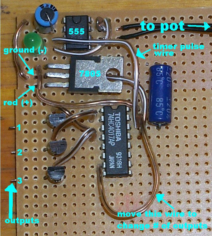
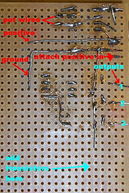
The following are pictures of the circuit I built for a friend. This circuit uses transistors because he was going to connect it to relays. Please note this circuit has only 3 outputs. However, room has been made to add more. I also added a 7805 voltage regulator to produce the +5VDC necessary to operate the circuit. The big blue thing on the right of the 7805 is a 22uF filter capacitor for the voltage regulator. The round green thing is a LED which shows the 555 is operating (it flashes) and sending timer pulses to the 4017. You don't need to have it but it does help with troubleshooting. It is wired between pin 3 of the 555 and ground. In case you're wondering, the left picture is a top view of the board and the right picture is a bottom view of the same board:
Troubleshooting
If things aren't working the way they are supposed to, get an LED and place the positive (longer) lead on pin 3 of the 555 and the negative (shorter) lead on ground. It should blink. If not then the problem is located in your 555 circuit and not the 4017.
If the LED is blinking then remove the LED and remove the transistor connected to the first output of the 4017. Place the positive (longer) lead of the LED on the first output pin of the 4017 and the negative (shorter) lead on ground. The LED should come on and then go off for a long period of time and then repeat. You could place LED's on all the outputs of the 4017 to check and make sure the 4017 is behaving correctly. Simply remove all transistors and replace each with a LED. If the LED's are cycling properly then the problem is either with the transistor(s) or the relay(s).

Return to HOME
Last modified on 02/01/01